A single hydrant valve is easy to misidentify: it is usually one hose outlet within a larger hydrant installation, not the pump, riser, isolation point, or complete hydrant box. By the end, you will be able to identify its parts, trace its connection from tank to hose, compare single and double outlets, and check whether a proposed valve suits the pressure, coupling, and installation.
Key takeaways
- A single hydrant valve provides one hose connection, not a complete hydrant assembly.
- Choose single or double outlets according to hose access and system demand.
- Match the valve connection, pressure rating, hose coupling, and pipework.
- Verify materials, certification, dimensions, seals, and installation records before acceptance.
What a single hydrant valve contains and where it sits
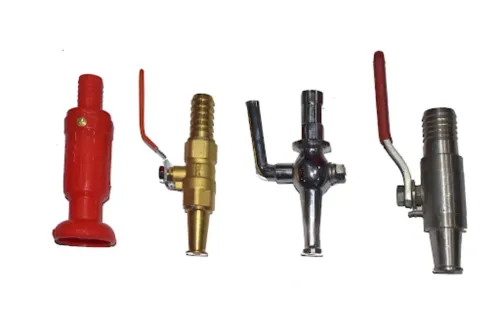
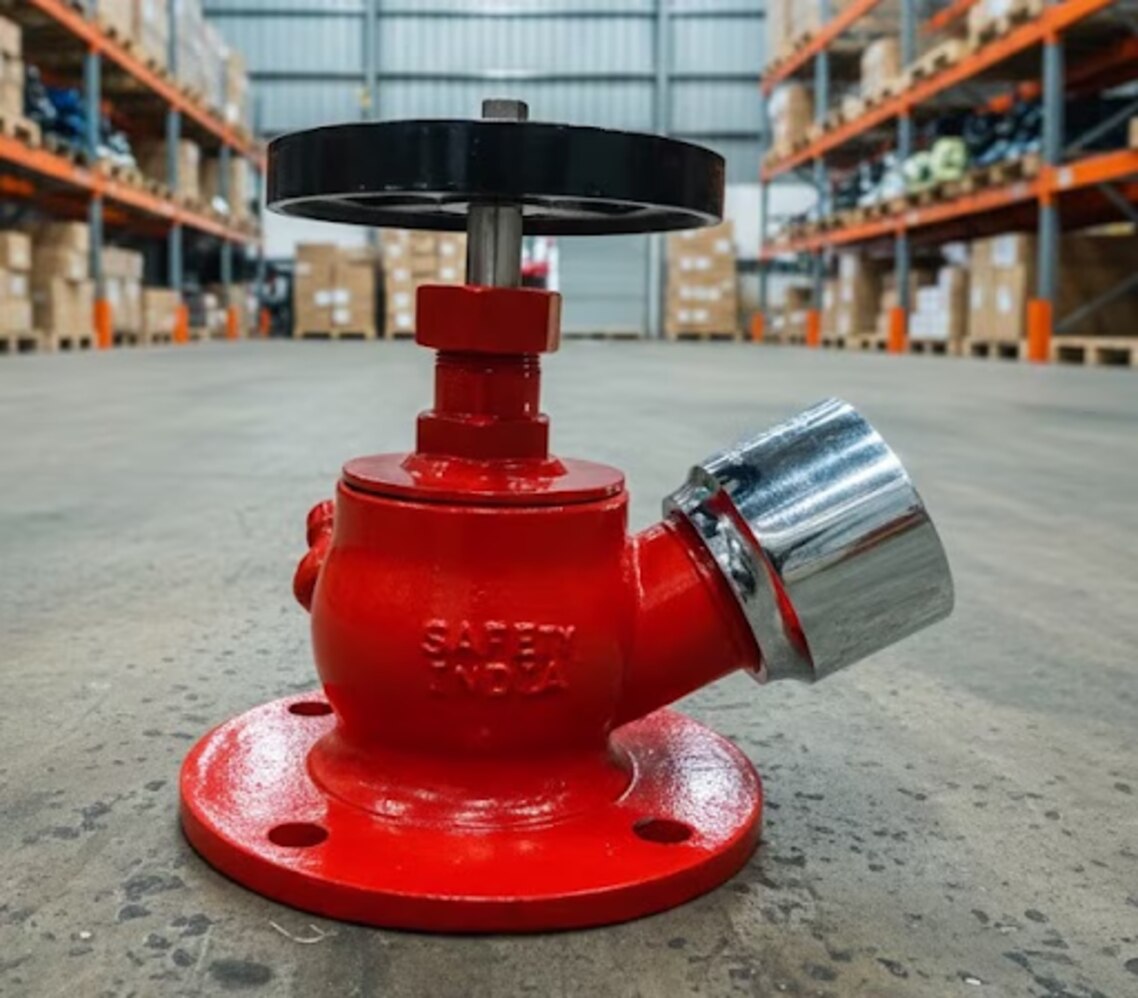
A single hydrant valve provides one hose connection; it is not a complete hydrant assembly. Its hydrant valve parts are:
- Valve body with an inlet connected to the riser or branch pipe
- Outlet facing the hose
- Bonnet and spindle operated by a handwheel or approved operating mechanism
- Sealing elements, including the seat and spindle seal
- Cap and chain protecting the outlet when unused
- Hose connection matched to the specified coupling
The valve normally sits at a landing-valve point on a wet riser, dry riser, external hydrant line, or other hydrant arrangement. Trace the system from the water tank and fire pump through the pump discharge and riser to the valve, then through the hose, branch pipe, and nozzle.
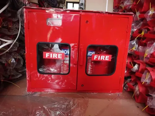
The hydrant box stores the hose and branch pipe; it does not turn the valve into a complete hydrant assembly.
“Single outlet” describes the number of hose connections on that valve, not the number of hydrant points in the building. A high-rise building can have one single-outlet valve on every floor. A double valve has two outlets at one point, but selection depends on coverage, staffing, cabinet space, and hydraulic calculations.
Do not confuse the hose valve with the riser isolation valve, pump control valve, or hose-reel valve: those serve different parts of the fire-protection system.
How the valve is used during and after a fire response
During hydrant valve operation, treat the outlet as a controlled water source, not as a substitute for the riser’s main isolation point. A trained operator must manage the hose, branch pipe, and nozzle before admitting full pressure.
1. Confirm that the hose coupling is fully seated on the outlet and that its gasket is present, clean, and undamaged. A poor seal can leak or separate when pressure rises.
2. Connect the hose, deploy it without sharp bends, and keep the branch pipe under control. The operator must brace the branch pipe before opening the valve because hose reaction force pushes the nozzle backward.
3. Open the valve fully, rather than throttling it halfway. Partial opening can damage the valve seat and creates turbulence; a high-pressure outlet can make the hose difficult to handle, so use the approved pressure-regulating arrangement where required.
4. After the response, close the valve gradually to reduce water hammer. Drain the hose and reset the cap, chain, hose, and associated drain or control arrangement according to the site procedure.
The operating outlet must not be confused with other valves. The isolation valve versus hydrant valve distinction is simple: an isolation valve controls a section of pipe, while the hydrant valve supplies the hose connection. An alarm valve manages waterflow alarm operation in a sprinkler installation, and a hose-reel valve serves the smaller hose-reel assembly.
Do not substitute any of them for a landing-valve hose connection without approved design.
Single outlet or double outlet: which arrangement fits the location?
Choose a single hydrant valve versus double hydrant valve by matching the outlet count to the coverage calculation, staffing plan, and adopted hydraulic design. A single valve provides one hose outlet, while a double valve provides two hose outlets at one hydrant point for simultaneous hose deployment.
| Arrangement | Space and equipment effect | Hydraulic and operational consequence |
|---|---|---|
| Single valve | Smaller hydrant box dimensions; less cabinet width, door-swing space, handwheel access, and branch-pipe clearance | One hose team operates; lower local pipe capacity, pump demand, and pressure loss |
| Double valve | Larger cabinet and riser space; two hose connections need separate hose storage, outlet orientation, door clearance, and working room | Two teams can operate together, but the supply must support simultaneous flows and the design must account for added pressure loss |
| Multiple single valves | Separate compact locations can use smaller cabinets and clearer access | Several landing-valve points can cover a large building without placing two outlets at one point |
A double valve is not automatically better. It can obstruct hose removal or handwheel access if the cabinet is narrow, and two outlets are useless when staffing or water supply supports only one operating line.
Use a single-outlet valve where one hose connection is required at each landing-valve location; install multiple single valves when the protected area needs broader coverage. Verify the arrangement against the hydraulic drawings rather than selecting it from cabinet size alone.
How to match the valve to the pipe, hose, and pressure calculation
A 2½-inch hydrant valve connection size at the pipe does not prove that the hose coupling fits. Specify the nominal inlet size and outlet size separately, then match each connection to the drawings and hose assembly.
1. Record the inlet size and confirm whether it uses a threaded or flanged connection. Record the outlet size separately and identify its thread, flange, or coupling pattern.
2. Name the hose coupling standard, such as a BS 336 coupling, a 1½-inch or 2½-inch NFPA-based connection, or a local equivalent. Confirm outlet orientation, cap, chain, and clearance for the connected hose and branch pipe.
3. Request the pressure rating, body and trim material, and gasket material. Check gasket compatibility with the service water, test medium, temperature, and any treatment chemicals; a leaking gasket can defeat an otherwise correctly sized valve.
4. Enter the system working pressure, test pressure, pump discharge pressure, and calculated pressure loss through the valve and hose. Use the manufacturer’s flow coefficient, equivalent length, or published loss data in the hydraulic calculation, not nominal size alone.
5. For NFPA 14 designs, check the adopted edition and system class. Approximately 65 psi minimum residual pressure at a 1½-inch hose connection and 100 psi at a 2½-inch Class I connection are common design criteria, not universal valve ratings.
If available pressure exceeds the permitted hose-valve limit, specify a listed pressure-regulating hose valve or approved pressure-control arrangement. Do not substitute an ordinary gate or angle valve; excessive outlet pressure can make the hose dangerous to control.
Selecting and verifying the valve for the actual installation
Select the valve against the installed arrangement, not from its body pressure marking alone. Wet riser, dry riser, external hydrant, and landing-valve installations expose the valve to different water, weather, access, and drainage conditions.
| Installation | Checks that can disqualify the selection |
|---|---|
| Wet riser valve | Confirm continuous water availability, pressure at the remote outlet, and supervised control valves. A hose outlet that opens without design pressure is not adequate. |
| Dry riser valve | Check pipe slope, auxiliary drains, caps, and sections where water could become trapped and freeze. A dry riser valve does not provide freeze protection. |
| External hydrant | Assess corrosion, vehicle impact, drainage, and clear access for hose connection and operation. |
| Landing valve | Check the cabinet or recess with the actual hose, coupling, branch pipe, and nozzle. Verify depth, handwheel clearance, hose-rack position, door swing, nozzle removal, and accessibility. |
During commissioning, record static pressure, residual pressure, and flow at the hydraulically remote outlet. Test the associated control and drain arrangements, not only the pump or tank.
In India, compare the selection with NBC 2016 Part 4, the fire consultant’s hydraulic drawings, and the requirements of the relevant state or municipal fire authority. Confirm the project’s required approval or listing; a stamped pressure number does not prove suitability.
When comparing Safety India Service 27CNOPP6823R1ZV with another supplier, request the exact model, approval documents, pressure and loss data, material specification, coupling details, and test records, then match them against the installation schedule.
Related product
 | Single Hydrant Valve The Single Hydrant Valve by Safety India Service is a high-performance fire safety component designed to ensure reliable water supply during... View product → |
Frequently asked questions
What does a single hydrant valve contain, and where is it installed?
A single hydrant valve contains one hose outlet, a valve body, an operating mechanism, a cap or blanking arrangement, and sealing components. It sits on the hydrant branch or landing-valve connection, forming one part of the wider hydrant assembly.
How is a single hydrant valve used during and after a fire response?
During a response, trained personnel open the valve gradually, connect the hose, and control the water flow while checking for leaks and unsafe pressure changes. Afterward, close the valve, drain or manage trapped water, replace the outlet cap, inspect seals, and record defects.
Should you use a single-outlet or double-outlet hydrant valve?
Use a single outlet when one hose line provides the required access and flow. Choose a double outlet when the layout, response plan, or hydraulic calculation requires two hose connections at the same hydrant point.
How do you match a single hydrant valve to the pipe, hose, and pressure calculation?
Confirm the pipe diameter and joining method, match the outlet coupling to the hose connection, and check the valve's rated working pressure against the system design pressure. Include friction loss, elevation, simultaneous flow, and available pump pressure in the calculation.
What should you verify before selecting a single hydrant valve?
Check the valve material, nominal size, outlet coupling, pressure rating, dimensions, thread or flange details, seals, operating direction, test documentation, and compatibility with the installed hydrant system.