A fire hydrant installation is a connected water-delivery system, not a collection of red cabinets and valves. By following the water path, separating each component’s job, and checking design, markings, testing, and compatibility, you can assess whether a proposed system will deliver usable firefighting water where it is needed.
Key takeaways
- Use a jockey pump for standby pressure and a diesel pump for backup fire flow.
- Choose hydrant, wet riser, dry riser, or combined protection from building height and risk.
- Match hose, nozzle, landing valve, and inlet to the outlet and design flow.
- Check pump duty, storage volume, pressure, access, labels, and inspection records.
How water travels through a complete fire hydrant system
Water leaves the water storage tank through the suction pipe to the pump set. The fire pump supplies the design flow; the jockey pump maintains standby pressure and limits unnecessary main-pump starts. A diesel backup pump provides fire flow when the duty pump or its power source cannot meet demand.
Non-return valves stop reverse flow, while isolation valves allow servicing without dismantling the system. Pressure gauges show suction and delivery conditions, and the delivery pipe carries pressurised water into the riser. In a multi-storey building, the riser feeds each protected floor and its outlet assemblies.
The water’s final route depends on the connected fire hydrant system components:
- A landing valve sends water through a hose to a branch pipe or nozzle, allowing firefighters to direct a solid jet or spray.
- A hose reel supplies a permanently connected small hose and nozzle for first-response firefighting; it is not a replacement for a hydrant hose assembly.
- A sprinkler connection feeds individual sprinkler heads through control valves, alarm devices, and branch pipework. Heat opens the sprinkler head, not the hose outlet.
- A fire brigade inlet, also called a fire department connection, lets responders add water to the correct system through a check valve. It supplements the tank and pumps; it does not replace them.
A test-and-drain assembly verifies flow and releases trapped water safely. The tank must provide usable volume for the required flow and duration, not merely a large-looking capacity.
Which fire protection arrangement suits the building?
Choose the arrangement by building height, access, occupancy, and whether firefighters need water inside, outside, or both. Standpipe Class I, II, or III identifies hose-connection sizes, not whether the riser is wet or dry; confirm the design with the adopted fire code and authority having jurisdiction.
| Option | What it provides | When it applies |
|---|---|---|
| Wet riser | Water-filled vertical pipe with pressurised landing valves | Multi-storey buildings where internal firefighting water must be immediately available |
| Dry riser | Normally empty vertical pipe charged through a fire brigade inlet | Buildings where firefighters supply water from outside; provide accessible valves, drainage, and cold-weather protection |
| Down-comer system | Vertical pipe, commonly supplied from an elevated tank, with floor-level landing valves | Buildings whose approved design permits a gravity-fed internal firefighting arrangement |
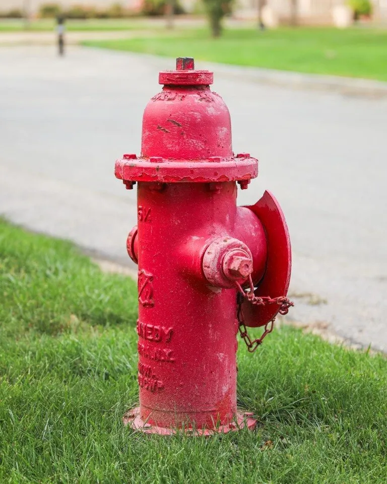
| Yard hydrant system | Outdoor hydrants connected to private site pipework | Campuses, factories, warehouses, and large plots needing hose access around buildings |
| Automatic sprinkler system | Heat-operated heads that release water at the fire location | Buildings requiring automatic control of developing fires; it complements, rather than replaces, required standpipes |
A wet riser needs a reliable tank, pump, and power arrangement. A dry riser depends on a fire engine or approved inlet, so a blocked or wrongly connected fire brigade connection can defeat it. Yard hydrants and sprinklers need separate hydraulic checks; combining systems does not remove the need to prove flow, pressure, and coverage.
What each outlet, valve, hose, and inlet is actually for
A single hydrant valve, landing valve, hose reel, and fire brigade inlet are connection points with different jobs; matching only by nominal diameter can leave firefighters with the wrong flow, coupling, or reach.
| Component | Actual job | Interchangeability and matching |
|---|---|---|
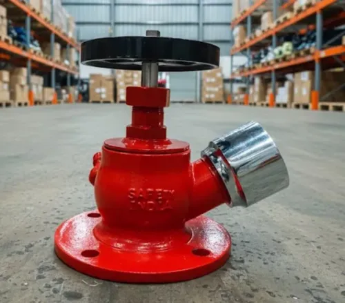
| Single hydrant valve | Controls water from a yard hydrant outlet to a hose. | Match the hydrant outlet thread or flange, pressure rating, material, and system flow; do not substitute a landing valve without checking the connection and approval. |
| Landing valve | Provides a fixed riser outlet, commonly for a 1½-inch or 2½-inch fire hose. | Select the size and pattern specified for the standpipe, with marking such as IS 5290 where required. It is not a hose reel valve. |
| Hose reel and hose reel nozzle | Delivers a controlled, continuous jet for first-aid firefighting. | Keep its hose length, bore, nozzle flow, and inlet connection as one matched assembly; it cannot replace a 2½-inch attack hose. |
| Branch pipe nozzle | Directs and controls the stream from a larger fire hose. | Match its inlet to the hose coupling and its flow to the landing valve and hydraulic design; a hose reel nozzle is not an equivalent. |
| Fire brigade inlet (FDC) | Lets responding crews supplement the connected system from outside. | Connect it to the correct riser or sprinkler system, with check valve, caps, signage, and accessible isolation arrangements. It is not a water tank or pump substitute. |
Use the correct hose coupling at every joint. A coupling that fits physically can still restrict flow or fail under pressure; verify thread, gender, standard, gasket, and working-pressure rating. Keep the hydrant box large enough for the specified hose, branch pipe, nozzle, and coupling without sharp bends.
How hydraulic design determines size, pressure, and pump duty
Static pressure is not proof that the hydraulically most remote outlet will deliver the required residual pressure. Hydraulic design tests the whole route from tank to outlet under the building’s worst operating condition.
Collect these inputs before selecting equipment:
- Building height, floor area, and hazard classification establish the protected zones, outlet demand, sprinkler design density, and required duration.
- Simultaneous demand defines which hydrant, hose reel, standpipe, and sprinkler connections operate together, producing the required flow.
- Pipe lengths, diameters, materials, fittings, valves, strainers, and non-return valves determine pipe friction loss.
- Floor-to-floor elevation creates elevation loss; the highest or most remote outlet usually controls the calculation.
- Tank usable volume, suction level, refill rate, and suction arrangement prove that water remains available for the design duration.
- The pump duty point must match the calculated flow and pressure after suction pressure, elevation loss, pipe friction loss, churn pressure, and test-line losses are considered.
- Outlet pressure checks must include lower floors, where excessive pressure may require a pressure-reducing hose valve or another approved pressure-control arrangement.
| Design input | What it proves | Failure if ignored |
|---|---|---|
| Building height and outlet elevation | Available static head and elevation loss | Remote outlets lack residual pressure |
| Hazard classification and simultaneous demand | Required flow for hydrants and sprinkler connections | Tank and pump are undersized |
| Pipe route and fittings | Pipe friction loss at design flow | Pressure collapses at the outlet |
| Pump curve and duty point | Pump performance at required flow and pressure | Flow or pressure is inadequate |
| Tank volume and duration | Continuous water supply | The pump runs dry before firefighting ends |
How to specify, identify, and keep the system ready
Do not accept a fire-protection component because its nominal diameter matches the pipe. Verify its pressure rating, material, temperature limit, connection standard, fire-service approval, and compatibility with the complete assembly; a fitting rated for general plumbing can fail under pump surge.
1. Read the permanent marking on every valve, pipe, hose, nozzle, and inlet. Record the manufacturer, model, nominal diameter, pressure rating, material, batch information, and test pressure. Reject unmarked items or components whose markings do not match the submittal and approval documents.
2. Check each valve’s job and normal position. An isolation valve enables sectional shutoff, a non-return valve prevents reverse flow, and an alarm valve triggers waterflow notification where specified.
Confirm valve supervision, accessible valve indicators, locked or sealed open positions, and clear labels; a closed riser or suction valve can disable protection without an obvious leak.
3. Inspect the fire brigade connection: correct system connection, inlet check valve, caps, threads or couplings, signage, drainage, and unobstructed access. It supplements the fire pump and tank; it does not replace either.
4. Demand signed inspection, testing, and maintenance records, pump test results, alarm tests, valve-position checks, flushing records, and defect closures. Compare the design and records with IS 13039, IS 3844, and IS 15105, plus the approving authority’s conditions.
Safety India Service can help you match a single hydrant valve to the specified connection, pressure class, and maintenance documentation instead of selecting by appearance alone.
Related products
 | Single Hydrant Valve The Single Hydrant Valve by Safety India Service is a high-performance fire safety component designed to ensure reliable water supply during... View product → |
 | Pendent Sprinkler The Pendent Sprinkler from Safety India Service is a reliable and high-performance fire-protection device designed for maximum safety in residential,... View product → |
Frequently asked questions
How does water travel through a complete fire hydrant system?
Water moves from the storage tank through the suction pipe to the fire pump, then through the riser and branch pipe to outlets. The jockey pump maintains standby pressure, while the diesel pump supplies fire flow if the duty pump or its power source fails.
Which fire protection arrangement suits a building?
Select a wet riser, dry riser, hydrant, or combined arrangement according to building height, occupancy, fire load, access for fire services, and local design requirements.
What are hydrant outlets, valves, hoses, and inlets used for?
Landing valves provide hose connections at protected levels, hoses carry water to the fire, nozzles control the discharge pattern, and breeching inlets let fire-service vehicles supplement the system.
How does hydraulic design determine pump size and pressure?
Hydraulic calculations set the required flow and residual pressure at the hydraulically most remote outlet. Pipe diameter, friction loss, elevation, storage, and pump duty must then support that demand.
How do you keep a fire hydrant system ready?
Keep valves accessible and labelled, maintain clear hose cabinets, test pumps and alarms, inspect tanks and pipework, record pressures and flow results, and replace damaged or expired components.
Related products
 | Hose Reel Nozzle Safety India Service offers a premium-quality Hose Reel Nozzle designed to deliver efficient water flow and quick response during fire emergencies. View product → |
 | Double Door Hose Box The Double Door Hose Box by Safety India Service is a robust and reliable fire safety storage solution designed to keep fire hoses protected,... View product → |