A single hydrant valve cannot be selected safely from nominal diameter or a catalogue label alone. You need to match its system location, outlet coupling, hydraulic duty, pressure rating, construction, installation space, and approval evidence before ordering. By the end, you will have a practical sequence for specifying and checking the valve at site.
Key takeaways
- Confirm the firefighting class before choosing the outlet size.
- Use a 2½-inch outlet for a typical NFPA Class I standpipe connection.
- Check pressure, flow, temperature, pressure loss, and physical clearance.
- Request approval evidence and documented handover test results.
Start With the Hydrant Connection and Firefighting Class
A single hydrant valve is correct only after you identify the connection’s location and firefighting class. For an NFPA standpipe, a Class I standpipe connection normally uses a 2½ in (65 mm nominal) hose outlet for fire-department use. A single 1½ in (40 mm nominal) outlet can therefore create a non-compliant Class I arrangement.
Class II normally uses 1½ in, while Class III provides both sizes.
Single versus double hydrant valve is a system decision, not merely a purchase preference.
| Option | Outlet arrangement | Correct application |
|---|---|---|
| Single-outlet landing valve | One hose outlet | A defined hose connection requiring one specified hose size |
| Double hydrant valve | Two hose outlets | A connection requiring simultaneous access or two hose sizes |
| Underground or yard hydrant valve | External hydrant outlet | A standpost or yard hydrant, not automatically a standpipe landing valve |
Confirm that the product is a single-outlet landing valve, a standpipe hose valve, or an underground/yard hydrant valve before comparing sizes. These categories have different installation and testing requirements.
The valve’s fire-protection listing or approval must cover the purchased configuration, including outlet size and pressure-regulating function; a general plumbing angle valve is not an equivalent substitute.
Also check the user and environment. A fire-department connection needs the department’s hose coupling, while an exposed or unheated valve needs drainage, dry-system protection, or a listed dry-barrel arrangement to prevent trapped water from freezing.
Specify the Valve Body, Internals, Connections, and Accessories
Put the system location and user on the purchase specification: wet riser, dry riser, hydrant standpost, landing valve, or hose box. “Single hydrant valve” is not a universal category, and a general plumbing angle valve is not an acceptable substitute for a fire-protection hose valve.
Specify:
- Body material, corrosion-protection finish, nominal inlet and outlet sizes, angle pattern valve orientation, and handwheel material and clearance.
- Seat and spindle material, disc or ball arrangement, stem sealing method, drain provision, and replaceable-wear-part details.
- Maximum working pressure, hydrostatic test pressure, temperature range, and the manufacturer’s certified flow or pressure-loss data.
- Listing or approval scope for the exact configuration, including outlet size and any pressure-regulating function.
- Cap or plug, chain or tether, gasket, reducer, and compatible hose coupling as supplied accessories.
Connection choice affects both installation and emergency use:
| Connection type | Specify before purchase | Main check |
|---|---|---|
| Threaded inlet | Thread size, thread form, material, and nominal bore | Confirm it matches the riser or standpost without an incompatible adapter |
| Flanged inlet | Flanged connection, flange standard, nominal size, and pressure class | Match the mating flange, bolt pattern, gasket, and available installation space |
| Outlet coupling | Outlet size, coupling standard, cap thread, and hose interface | Confirm the site hose can connect directly and the cap remains tethered |
A smaller valve is not automatically easier to use. Check outlet direction, handwheel access, hose bend space, and cabinet or hydrant-pillar depth with the cap fitted.
Match Pressure, Flow, Temperature, and Pressure Loss
At least 100 psi (6.9 bar) residual pressure at the hydraulically most remote 2½ in hose connection is a common NFPA 14 design benchmark; a 1½ in connection commonly requires at least 65 psi (4.5 bar). The selected valve must preserve that pressure while delivering the calculated hose-stream flow. Nominal outlet size alone proves nothing.
Ask for these figures at the valve’s design flow:
- Working pressure, including the maximum pressure expected from the fire pump, standpipe, or pressure zone.
- Test pressure, covering the system hydrostatic or commissioning test without permanent deformation or leakage.
- Flow capacity and a manufacturer-certified pressure-loss curve, or the pressure loss coefficient with its reference diameter and flow units.
- Residual pressure range at the outlet, especially for a pressure-reducing or pressure-regulating hose valve.
- Allowable temperature range for the water and surrounding installation.
Use the valve’s pressure loss at the calculated flow in the hydraulic model. A reduced seat, sharp passage, outlet reducer, or regulating mechanism can consume more pressure than a full-bore valve, leaving the remote nozzle below its required residual pressure.
The factory test proves the individual valve, not the installed system. Confirm flow and residual pressure during acceptance testing at the remote outlet, with the hose, coupling, nozzle, riser, and pump operating as designed.
Check the rating against both working pressure and test pressure; an ordinary water-service valve can fail the pressure demand of a high-rise standpipe.
Check the Flow Path and Physical Fit Before Installation
Draw the fire pump to hose flow path on the installation plan before accepting the valve location. Show the pump, riser, single hydrant valve, hose, nozzle, and the route water takes to the fire.
1. Identify the system location: landing valve on a wet riser, outlet on a dry riser, or valve on a hydrant standpost. Confirm the inlet connection, outlet size, thread or flange, gasket, reducer, cap, chain, and hose coupling match the installed arrangement.
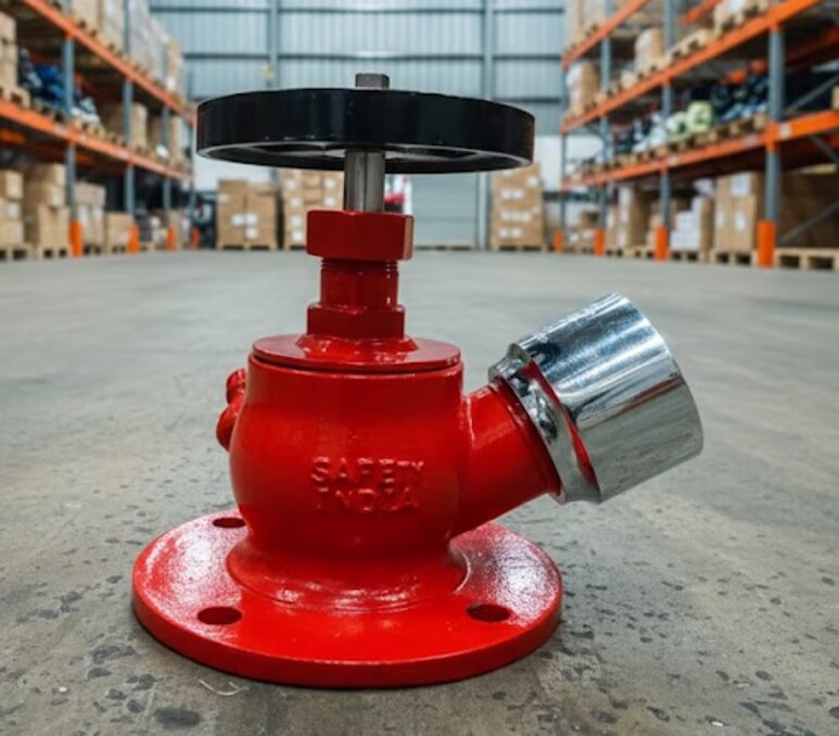
2. Dry-fit the valve with its cap and hose attached. Check that a 90-degree angle pattern points the hose toward the escape route without a sharp bend, and that the handwheel clears the cabinet, pillar, wall, and adjacent pipe. A smaller body is not automatically easier to operate.
3. Mark the operating height and standing space. Firefighters must reach the handwheel, remove the cap, connect the hose, and turn the valve fully without tools or obstruction. Keep doors, panels, vehicles, stored materials, and structural members outside that working area.
4. Provide a drain or drain-down route at the low point, with no trapped section between the valve and drain. After installation, open the valve under controlled conditions and confirm unobstructed flow, no leakage at joints, correct hose connection, and complete drainage without discharging water into the cabinet or access path.
Demand the Right Standard, Approval Evidence, and Handover Tests
The deciding evidence is the valve’s fire-protection approval scope, not its matching thread or pressure mark. Ask for the exact model, outlet size, connection type, pressure-regulating function, and intended hose-connection class.
| Document | Fire-protection hose valve | General-purpose plumbing valve |
|---|---|---|
| Standard or listing | Identified to IS 5290 where specified, with listing or approval covering the purchased configuration | Plumbing standard or no fire-service approval |
| Design basis | Suitable for the standpipe arrangement under NFPA 14, including 1½ in or 2½ in hose connection service | Rated for ordinary water distribution |
| Test certificate | Names the model, size, pressure, test method, result, date, and batch or serial number | May show only a generic plumbing pressure test |
| Regulating function | Pressure-regulating valve has fire-protection listing and a stated residual-pressure range | Ordinary reducing valve with no hose-stream approval |
Require the supplier’s factory pressure test certificate, but do not treat it as system acceptance. It proves the individual valve was tested; it does not prove thread compatibility, drainage, flow, or residual pressure at the hydraulically remote outlet.
At handover, record these checks:
- Confirm the valve opens fully, closes without leakage, and drains correctly.
- Verify the hose coupling fits the installed outlet.
- Measure flow and residual pressure at the remote connection against the hydraulic design and NFPA 14 values.
- Record installation location, model, batch number, and inspection schedule.
Ask Safety India Service to include those records with the supplied valve; a catalogue description cannot establish compliance.
Related product
 | Single Hydrant Valve The Single Hydrant Valve by Safety India Service is a high-performance fire safety component designed to ensure reliable water supply during... View product → |
Frequently asked questions
What outlet size does an NFPA Class I standpipe connection normally use?
An NFPA Class I standpipe connection normally uses a 2½-inch, or 65 mm nominal, hose outlet for fire-department use.
Which hydrant valve specifications must be checked before purchase?
Check the valve body material, internal components, connection type, accessories, pressure rating, flow capacity, temperature range, and pressure loss.
Why should you verify the valve’s physical fit before installation?
Confirm the flow path, pipe alignment, outlet orientation, operating clearance, connection dimensions, and access for hose attachment and maintenance.
What evidence should you request from the hydrant valve supplier?
Request the named standard or approval evidence, product identification, test records, and handover results for pressure and operational testing.